¶ Overview
An automated monitoring node (AMN) that interfaces with sensors, the AMN-MINI features two discrete GPIO inputs capable of connecting with a variety of sensors.
¶ Connectors
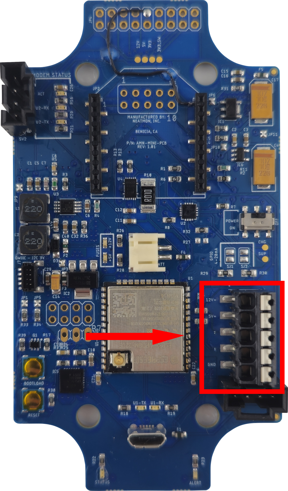
This is the sensor connector. To insert a wire, firmly push the wire into the port until it is fully seated. To remove a wire, use a small flathead screwdriver to push down the white pad adjacent to the port that contains the wire you wish to remove.
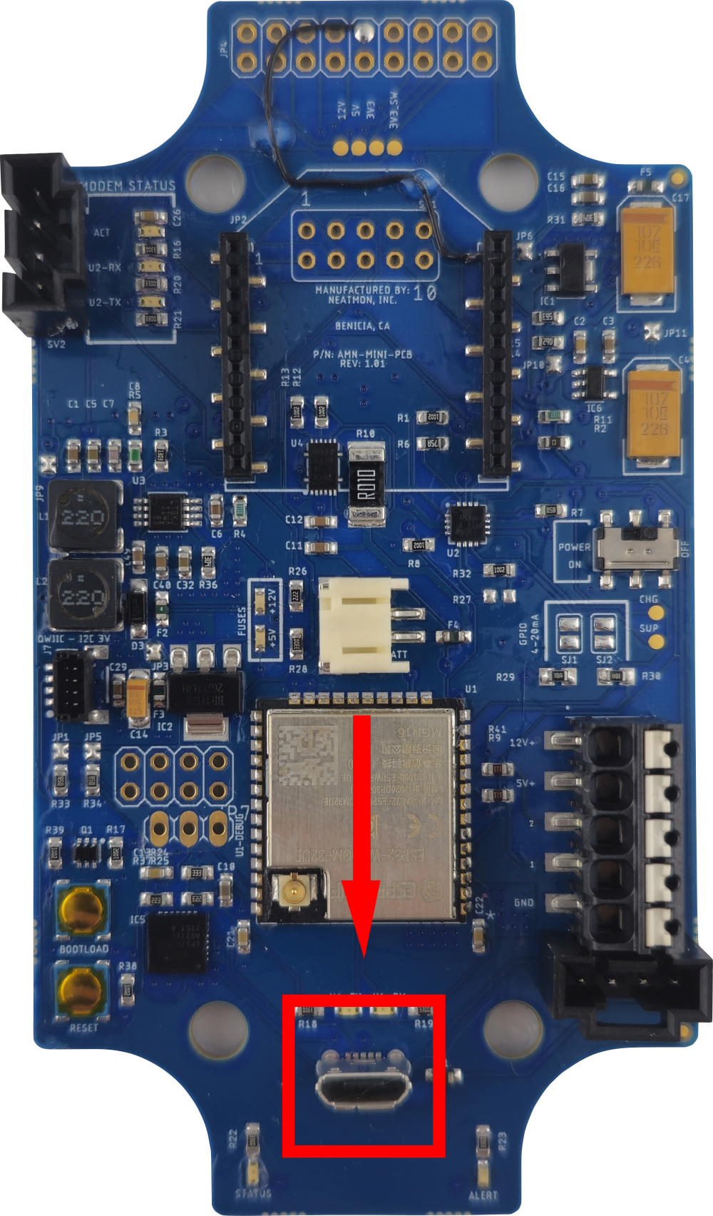
This is the micro USB port. It can be used to interface with the AMN from a computer and it can also be used for charging.
NOTE: Never have the solar panel plugged into the AMN at the same time as the USB cable.
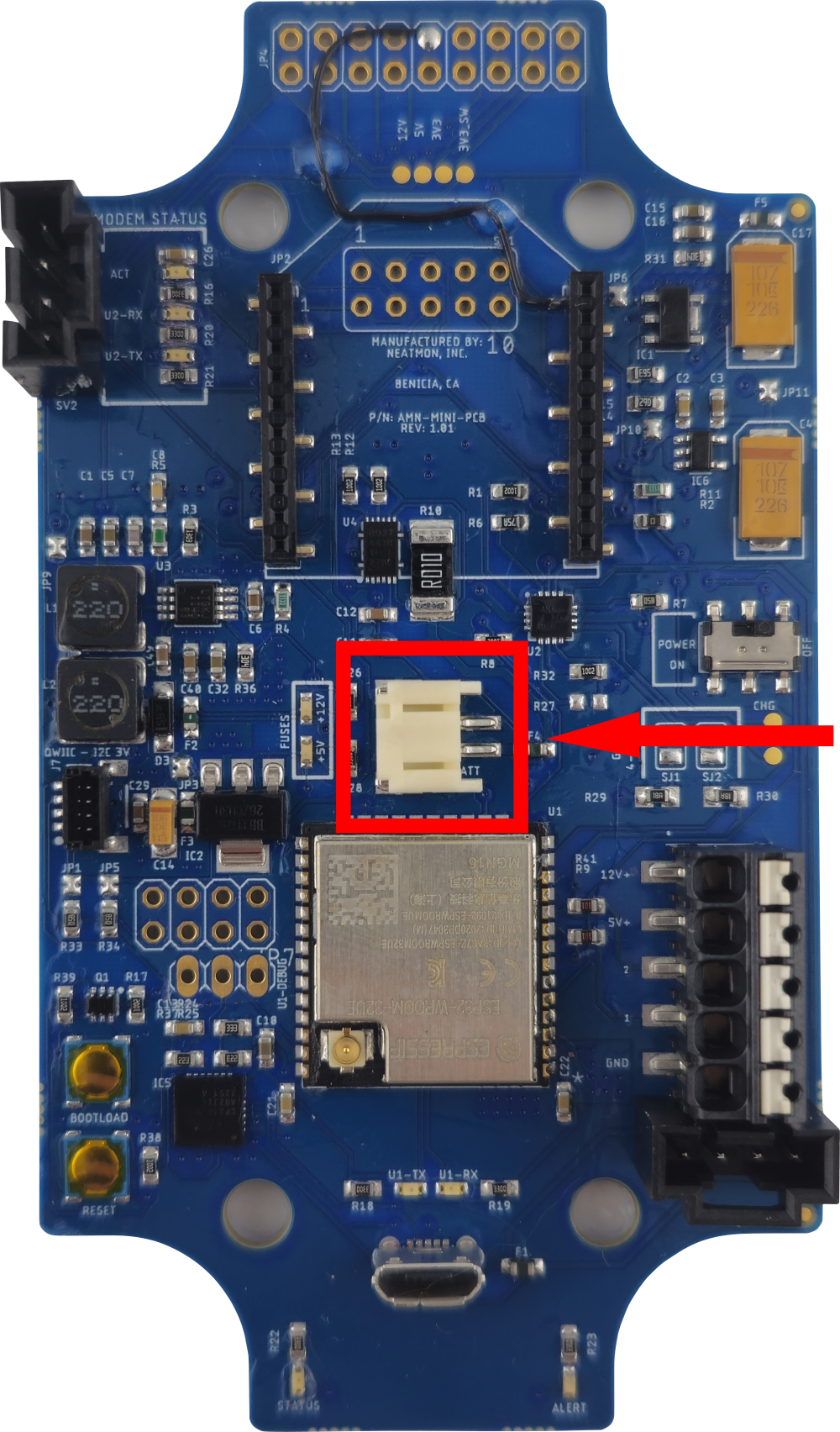
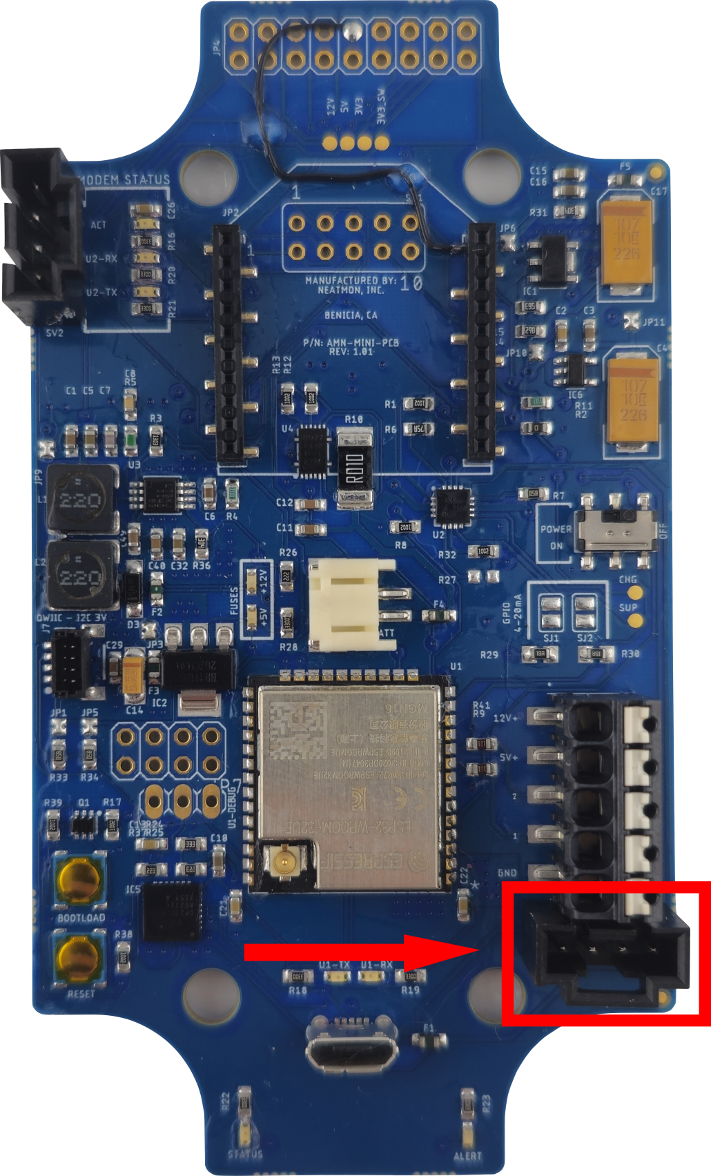
This is the battery connector. It is rated for a 3.7V battery.
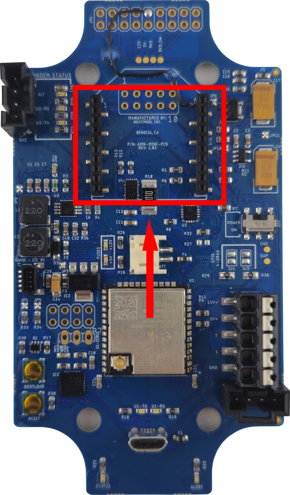
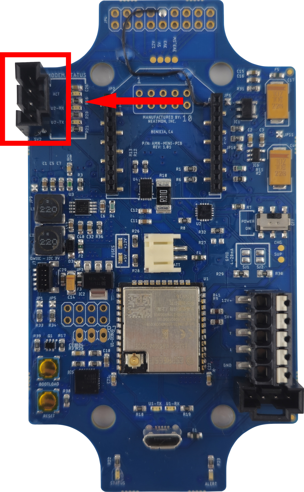
These connectors are used for interfacing with cellular modems.
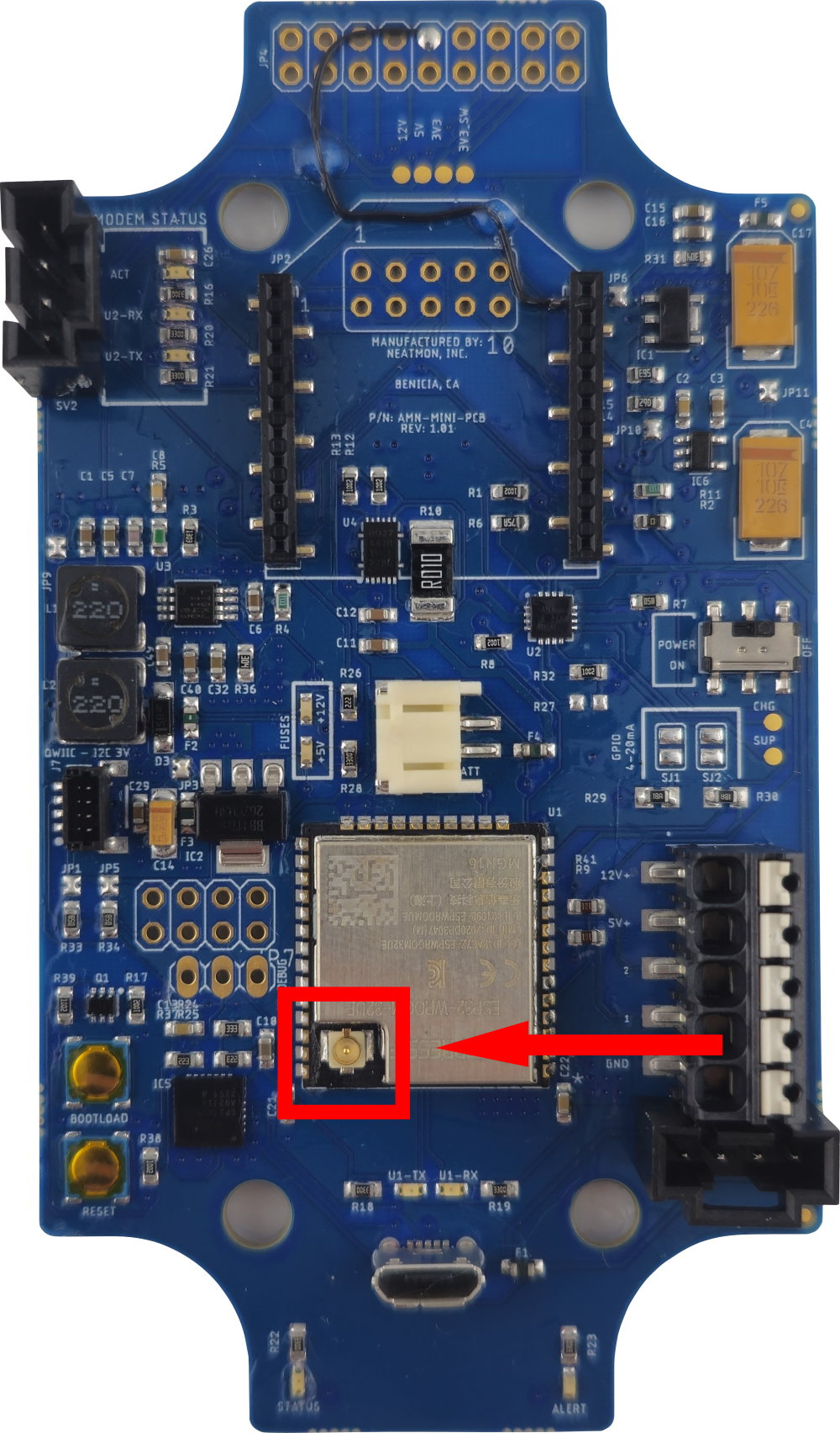
This is the WiFi antenna connector.
This is the connector for the status lights on the top of the AMN.
This is the solar panel power connector.
¶ Buttons and Switches
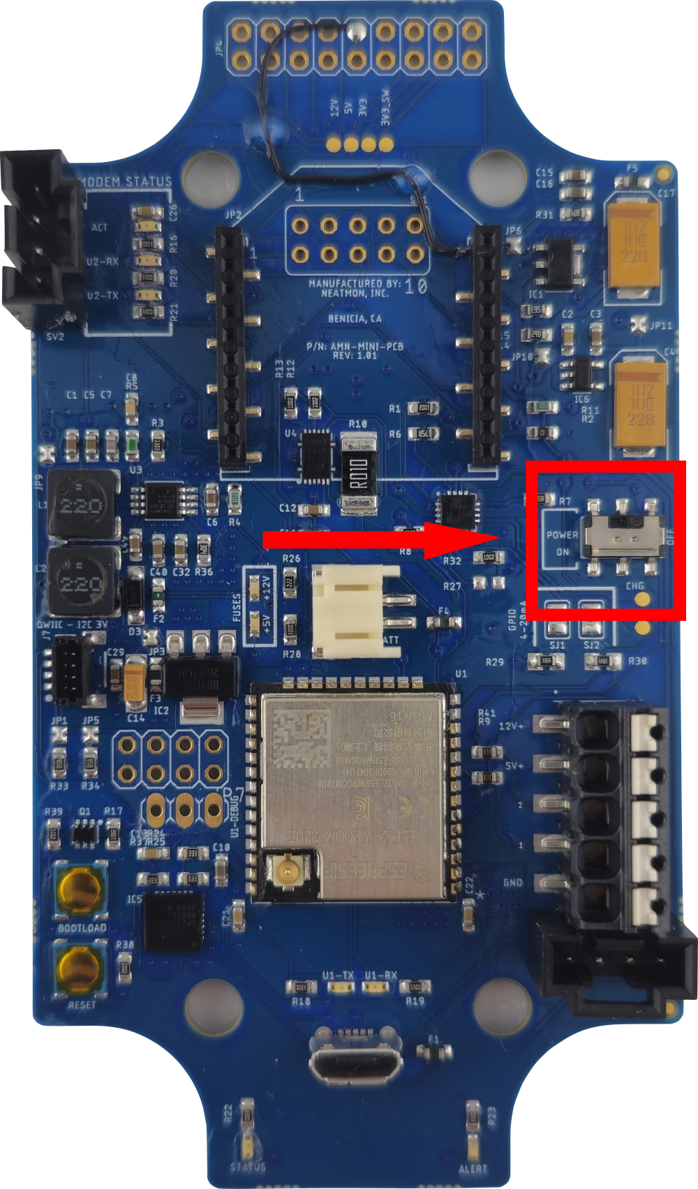
This is the power switch. This switch only controls battery power and will not turn off the unit if it is plugged in by USB.
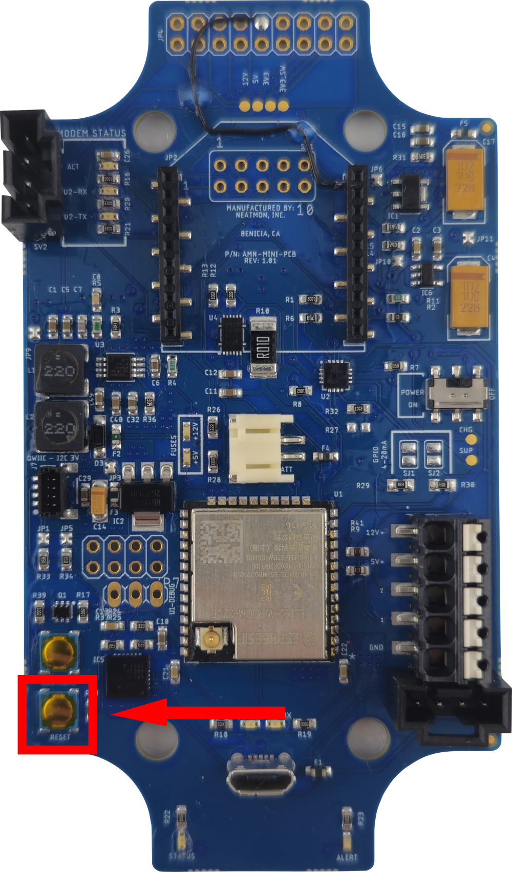
This is the reset button.
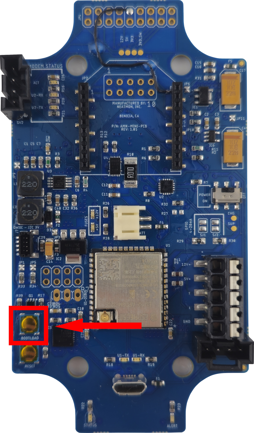
This is the bootload button. It is used for loading software onto the AMN.
¶ Lights
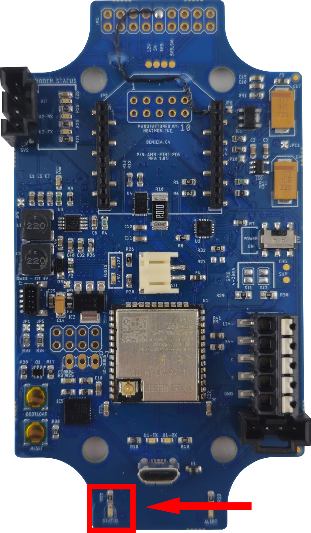
This is the status light. It will blink green while the AMN is running and not in sleep mode.
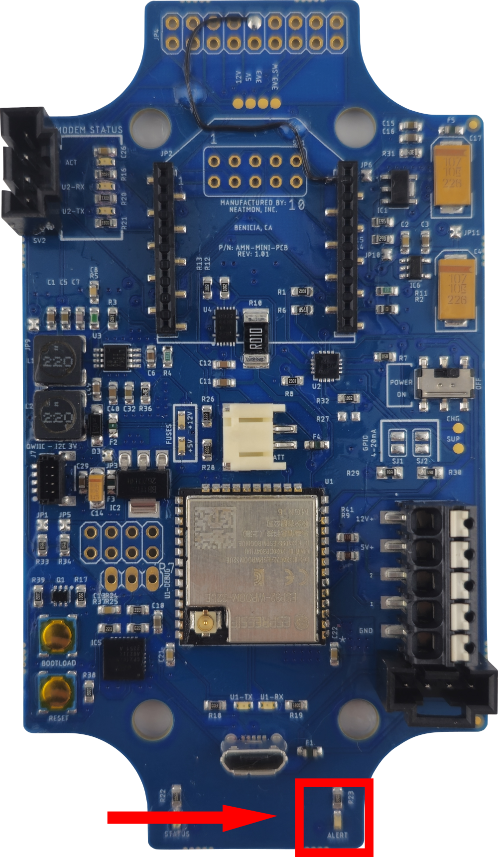
This is the alert light. It will turn solid red if the AMN has encountered an error.
¶ Proper Use
¶ Plugging in Battery
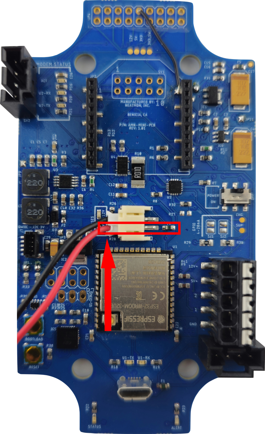
When connecting a battery to the AMN ensure the red (positive) wire is closest to you when the AMN is in the orientation shown above.
¶ Sensor Connector
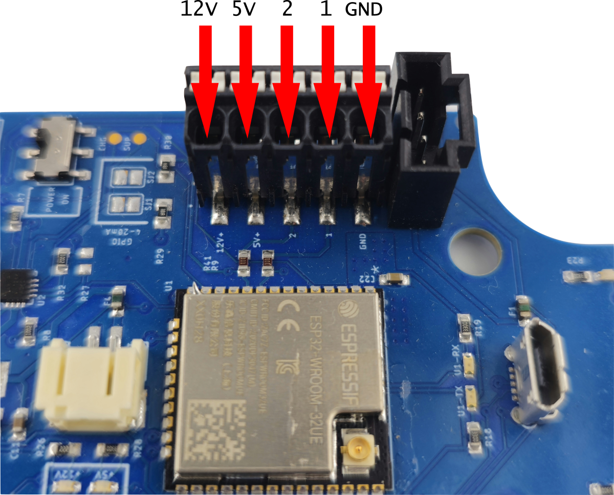
| Name | Description |
| 12V | Twelve-volt power for the connected sensor. |
| 5V | Five-volt power for the connected sensor. |
| 2 | Universal communication port that can be a clock port, data port, analog, or GPIO port. |
| 1 | Universal communication port that can be a clock port, data port, analog, or GPIO port. |
| GND | Ground (negative). |
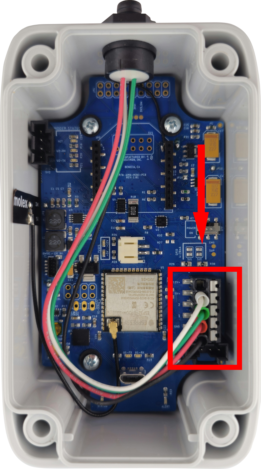
This is the IMX-8 plug wired to the sensor connector.
NOTE: The sensors do not have a function with a reverse polarity. If you do reverse the polarity it will void the warranty and possibly damage equipment.
| Color | Name | Description |
| White | 5V | 5-volt power |
| Green | 2 | Clock |
| Red | 1 | Data |
| Black | GND | Ground |
¶ Plugging in Solar Panel
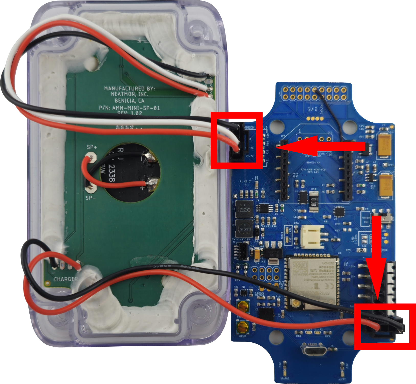
This is the way that the solar panel gets plugged into the AMN-MINI. Notice the cable with the white wire gets plugged in at the top of the board.
NOTE: Never have the solar panel plugged into the AMN at the same time as the USB cable.
¶ Installing Modem
¶ H-Modem
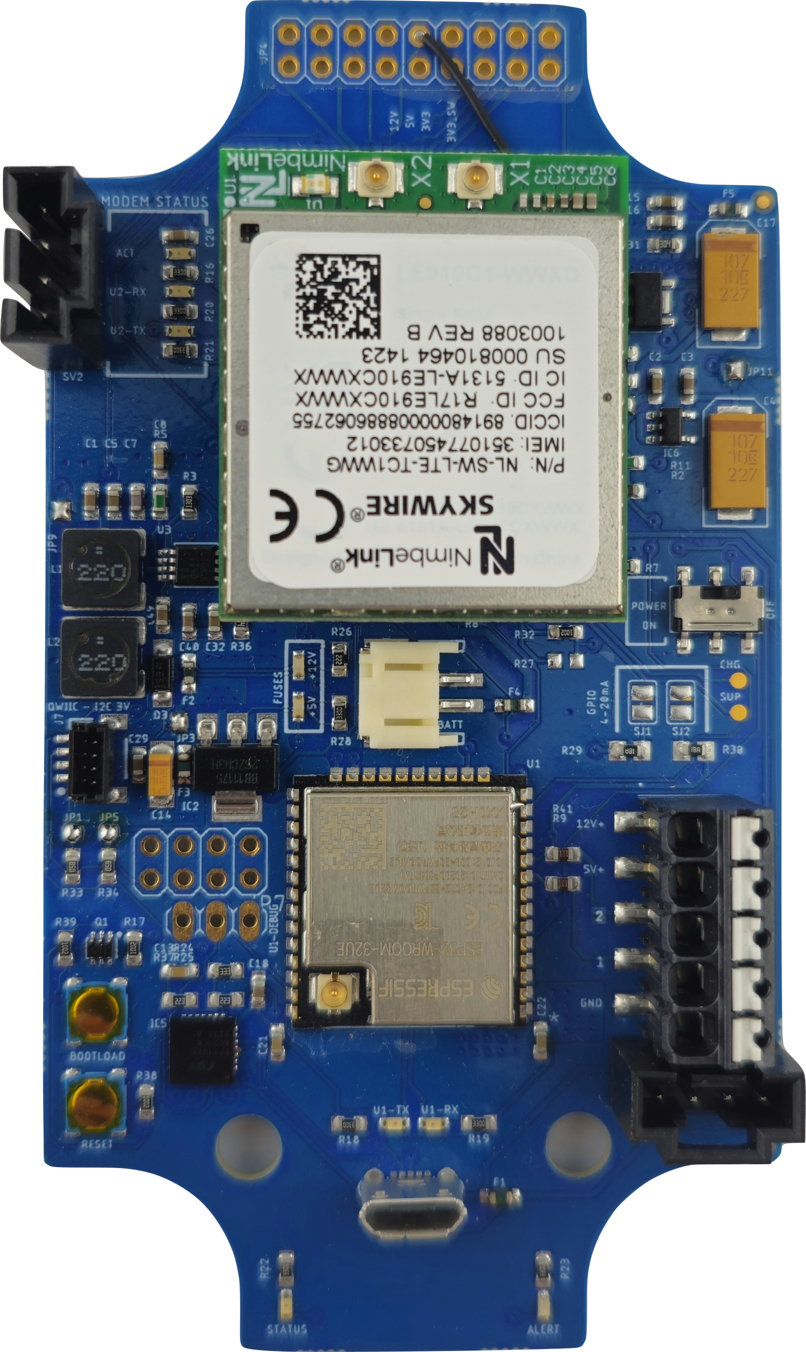
This is the modem orientation on the board for the H-Modem.
NOTE: Ensure the gold pins from the modem are aligned with the connectors on the AMN before pressing down to seat it into position.
¶ C-Modem
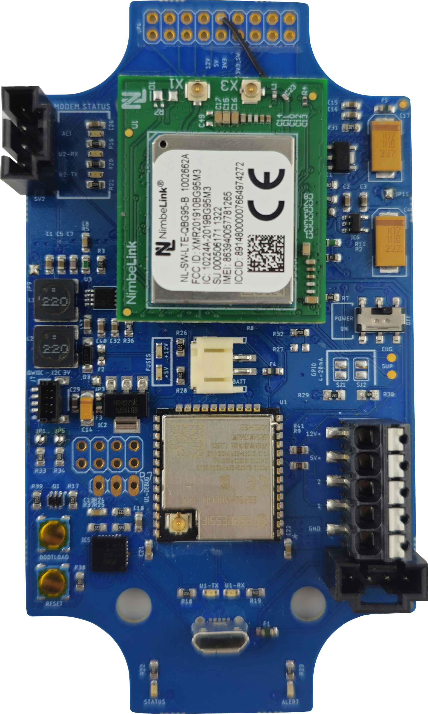
This is the modem orientation on the board for the C-Modem.
NOTE: Ensure the gold pins from the modem are aligned with the connectors on the AMN before pressing down to seat it into position.
¶ CT-Modem
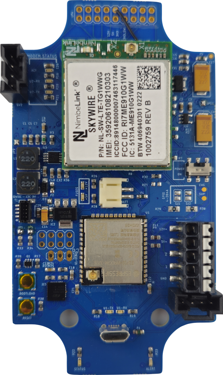
This is the modem orientation on the board for the CT-Modem.
NOTE: Ensure the gold pins from the modem are aligned with the connectors on the AMN before pressing down to seat it into position.