¶ Overview
The following guide provides an example for testing communication with the Automated Monitoring Node and a virtual Modbus device as emulated using the program Modbus Slave available for download here
Using an emulated Modbus device attached to an Automated Monitoring Node can be helpful for testing and setting up new devices.
¶ Setup
¶ Requirements
- Computer running Microsoft Windows
- USB to RS485 Adapter to connect with A/B ports
- USB to Micro USB Cable to connect with Automated Monitoring Nodes
¶ Installation
Install Modbus Slave software after downloading here
¶ Serial Configuration
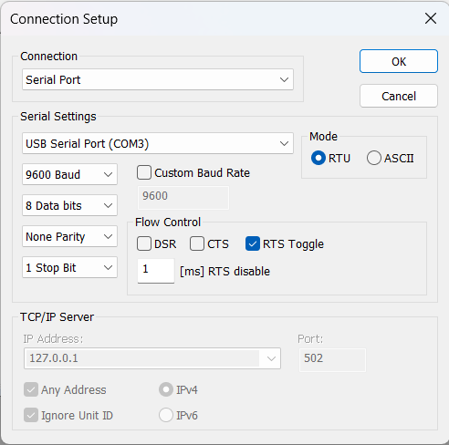
Open the Modbus Slave program. Choose ‘Connection’ from the menu → Connect
Select the COM port and configure it as shown in the screenshot below.

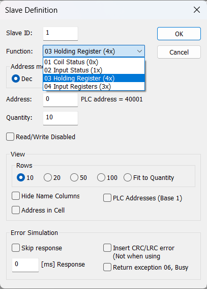
¶ Configure Slave Definitions
For this example, we will set it up according to the following screenshot. The final configuration will depend on the device that is ultimately connected

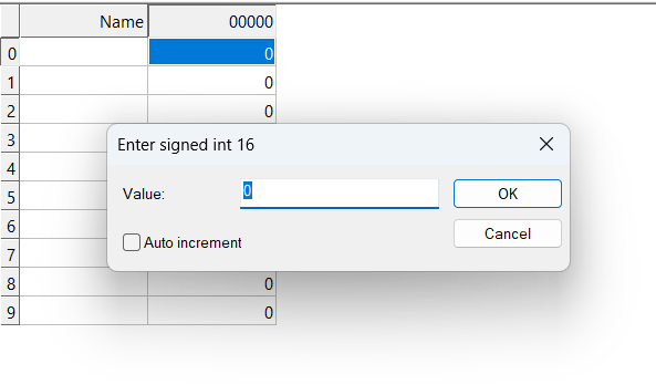
Double-click on the values next to each register address to change the stored value

¶ Configure Automated Monitoring Node
The test configuration for the AMN should be as follows
1. MBS:
        Type: mb [15]
        Sample rate (mins): 15
        Interface: ModBus
        Port: 0
        Misc:
    Serial Config: 9600 baud, 8 data bits, no parity, 1 stop bits (9600,8,n,1)
    Device ID: 1
    Read Address: 0x0
    Function Code: 3
    Bytes: 2
    Byte Format: Integer
Byte Order: MSB¶ Testing Communication
Enter the main menu of the Automated Monitoring Node by pressing the RESET button, then ‘C’ to enter the menu
Press 2 for the sensor menu
Press 5 to test read sensors, then select the sensor desired to read
¶ Troubleshooting
Most issues arise from incorrect configuration of the serial port, for example, baud rate, or stop bits. Double-check all connections and parameters. Additionally, the incorrect serial port could also be a source of confusion especially if there are many adapters in use.
Using the Communication Diagnostics in Modbus Slave program, it is possible to see the communication to attached devices. Click on the Menu Display → Communication, then review the commands sent to the attached sensor.