¶ Overview
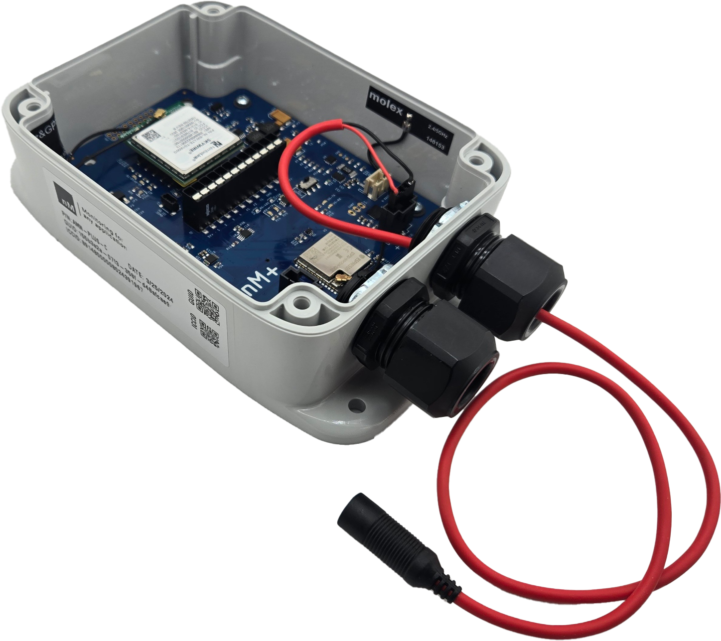
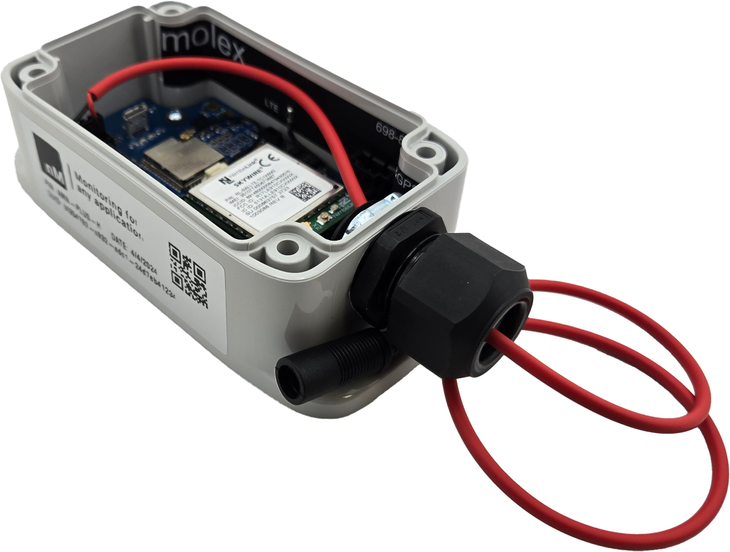
The following reference guides cover the setup and configuration of the neatMon Automated Monitoring Node (AMN) products.
The AMN is a hardware device designed to automatically monitor sensor inputs and send the calculated value to a remote server, where the data can be aggregated and displayed to users or used for edge computing purposes. Interested in sending the data to your own server? See the neatMon Open Source API in the Software Support section to learn more about the data model.
For a product comparison matrix, see the information at the bottom of this page. Need help setting up a device? See the Firmware Reference below.
¶ Useful Help Articles
We are always adding to the help articles. If you have an idea or would like specific information that you are unable to find, please get in touch with support
¶ Opening Bluetooth Terminal
Use a BLE wireless terminal program to communicate with the Automated Monitoring Node (AMN).
This interface allows you to set port configurations, test sensors, and debug communication issues directly from your device.
¶ USB Driver Download
The automated monitoring node requires a USB driver to connect to Windows-based computers. You can download the driver from the link here.
¶ Opening Serial Terminal
Use a serial terminal program to communicate with the AMN to set port configurations, test, and debug sensors or communications issues
¶ Updating Firmware by USB
When new features are needed, a firmware update can be used to add functionality. Newer firmware may be updated using the Over-The-Air function in the online software, or in some cases by cable, as this guide describes.
¶ Updating Configurations Using TeraTerm Macros
Updating a node using the serial terminal is a fairly straightforward process, as explained in the firmware reference below. However, to update many devices during provisioning, using a macro may be more expedient. This guide will give a basic overview of creating a script and how to run it.
¶ Firmware Reference
All models operate using the same firmware base, meaning that the commands and functions are the same. However, to save space in the device memory, each communication option, such as Wi-Fi, Cellular, or Satellite, has different firmware that will be loaded. Firmware and configuration references can be found below
¶ Firmware Command Reference
Command reference to set up, test, and debug using the nM AMN firmware.
¶ Debugging Cellular Connectivity
Reference to enable debugging of cellular connections.
¶ Node-to-Node Mesh Setup Guide
A setup guide for enabling node-to-node communication.
¶ WiFi Setup Guide
A setup guide for connecting to WiFi networks and testing connectivity
¶ Product Support Links
¶ Product Configuration Reference
Configuration options for the AMN allow for a wide variety of communication and sensor port options.
The AMN-PLUS features considerably more sensor connection options. It is recommended for installations requiring retrofitting, and or connecting user-provided sensors, as well as when many sensors are required at a single monitoring location.
¶ Communication and WAN Modem Options
Each AMN consists of a circuit board with a USB port for connecting directly to the node to set up, test, or debug.
For Wide Area Network/Cloud communications, each AMN is capable of communication via Wi-Fi and Bluetooth (BLE). The Automated Monitoring Nodes can be ordered from the factory or upgraded in-field with a replaceable modem to communicate with a cellular or satellite network.
Additionally, the AMN can communicate with Bluetooth sensors up to several hundred feet from the node.
The following is a matrix of modem options and frequencies used for each band. For more information on LTE bands and their corresponding frequencies and country list, see this wiki article

